Butt Fusion Machine Setup & Operation Guide for HDPE Pipes
Table of Contents
Butt fusion machines operating at 220°C with a precise 0.15 MPa interfacial pressure form the backbone of modern leak-free infrastructure. Yet, industry data suggests that 90% of joint failures stem from operator deviation rather than material defects. In the high-stakes environments of municipal water distribution, gas transmission, and mining slurry transport, the margin for error is nonexistent. A single failed joint can cost contractors upwards of $15,000 in excavation and re-work fees.
This guide covers essential butt fusion machine specifications, welding parameter standards (ISO 21307 vs. DVS 2207), step-by-step setup protocols, and critical troubleshooting techniques for industrial-grade equipment. We will walk you through the technical nuances of drag pressure calculation, generator sizing, and the economic impact of selecting manual versus CNC automation. By the end, you will have a clear framework to specify, setup, and operate equipment for DN90–DN1200 HDPE projects—and avoid costly specification mistakes.

—
Pre-Operation Setup: Safety, Power, and Environment
The reliability of a polyethylene pipeline is determined before the first arc of plastic is shaved. While the fusion principle is simple—heat, pressure, and time—the environmental variables surrounding butt fusion machines are complex. Ignoring site conditions or power stability is the fastest route to compromised weld integrity.
Site Preparation and Environmental Control
A common misconception in pipeline construction is that butt fusion machine can operate identically in a factory and a muddy trench. In reality, butt fusion machines are sensitive thermal instruments. According to DVS 2207 standards, welding must be suspended or protected if environmental conditions exceed specific thresholds. If wind speeds exceed 3.4–5.4 m/s (≥3 Beaufort scale), the airflow can strip heat from the heater plate and the pipe ends unevenly. This results in a “cold joint” where the melt temperature is insufficient for molecular fusion.
Operators must deploy welding tents or shelters to block wind, rain, and excessive dust. Moisture is the enemy of HDPE fusion; even a single drop of rain on the heating plate can create steam voids (porosity) in the joint wall. Regarding temperature, standard equipment is rated for ambient environments between -5°C and +40°C. When operating in sub-zero conditions, the butt fusion welding machine chassis requires pre-heating to ensure hydraulic fluid viscosity allows for smooth cylinder movement. Furthermore, pipe ends act as heat sinks; in extreme cold, Ekberg protocols recommend plugging the pipe ends to prevent wind tunnel effects and wrapping the fusion zone in cotton insulating blankets during the changeover phase to minimize heat loss.
Generator Sizing and Electrical Stability
Inconsistent power supply is a leading cause of premature component failure. A generator that is undersized will cause voltage drops when the hydraulic pump engages, potentially resetting the PID temperature controller or corrupting the data logger’s memory. The generator must be sized to handle the peak simultaneous load: the full resistive load of the heating plate plus the inductive startup surge of the hydraulic pump and the facing tool motor.
For modern CNC automatic butt fusion machines equipped with sensitive PLCs (Programmable Logic Controllers), voltage fluctuations can be catastrophic. We recommend generators with Automatic Voltage Regulation (AVR) to maintain a steady sine wave. Below is a sizing guide based on machine diameter and power draw:
Machine Inspection Checklist Before Power-Up
Before the generator is cranked, a rigorous mechanical inspection is mandatory. This prevents downtime mid-shift and ensures the hdpe pipe welding machine can physically deliver the required parameters.
1. Hydraulic Integrity: Check the HPU reservoir oil level. Inspect quick-couplers for dirt ingress; a single grain of sand can score a hydraulic valve, leading to pressure drift during the cooling cycle.
2. Facing Tool Condition: The planer blades must be sharp. Dull blades do not cut; they smear and compress the plastic, which can hide voids. If the shavings are not coming off as continuous, smooth ribbons, the blades must be reversed or replaced.
3. Heater Plate Surface: Inspect the PTFE (Teflon) coating. Non-stick integrity is vital. Scratches deeper than 0.1mm can cause the molten pipe face to stick to the heater during removal, ruining the joint geometry.
4. Clamp Alignment: Close the clamps without pipe to verify concentricity. The maximum allowable vertical misalignment (Hi-Lo) is typically limited to 10% of the pipe wall thickness.
—
Step-by-Step Operation Guide: The Fusion Cycle
Achieving a compliant weld requires strict adherence to the fusion cycle phases. This is not an art; it is a science governed by physics and thermodynamics. The operator’s goal is to replicate the standard’s requirements exactly, every single time.
Video: Step-by-Step Butt Fusion Machine for HDPE Pipe Welding
Phase 1: Pipe Preparation and Alignment (Clamping)
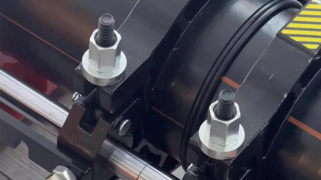
The process begins with securing the pipe segments. Once clamped, the operator must check for “Hi-Lo” misalignment. If two pipes are mismatched vertically, the resulting joint will have a stress concentration point that significantly reduces the pipeline’s pressure rating. On Ekberg hydraulic butt fusion machines, lateral adjustment screws on the chassis allow the operator to fine-tune the alignment to within the 10% wall thickness tolerance.
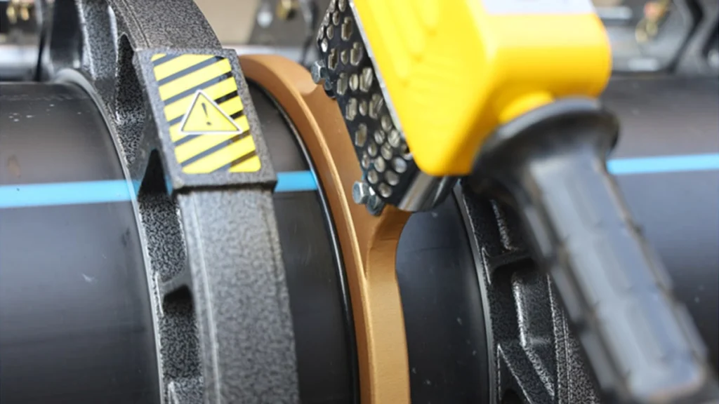
Next is the facing (planing) operation. The facing tool is inserted, and the pipe ends are pressed against the rotating blades. The goal is not just to flatten the pipe, but to remove the oxidized outer layer of plastic. Planing must continue until a continuous ribbon of polyethylene appears on both sides, spiraling out from the butt fusion machine. Once the tool is removed, the pipes are brought together for a gap check. The maximum allowable gap varies by diameter: 0.3mm for pipes under DN400, increasing to 0.5mm for larger diameters. Excessive gaps imply the cut was not square, which leads to uneven heating.
Phase 2: Heating and Soak Time Calculation
The heating phase is often misunderstood. It consists of two distinct sub-phases: Bead-Up and Heat Soak.
1. Bead-Up: The pipe ends are pressed against the heating plate (set to 210°C ± 10°C for PE100) under system pressure. This continues until a uniform bead of molten material forms against the heater, typically 0.5mm to 1.5mm high depending on the pipe size.
2. Heat Soak: This is critical. Once the bead forms, the pressure must be dropped to Drag Pressure only (effectively near zero). This allows the heat to soak deep into the pipe wall without pushing the molten material out to the sides. If high pressure is maintained during the soak, the “cold” core of the pipe never heats up, resulting in a brittle interface.
The soak time is generally calculated as 10 seconds per millimeter of wall thickness (DVS 2207). For a DN315 SDR11 pipe with a 28.6mm wall, the soak time would be approximately 286 seconds (nearly 5 minutes).
Phase 3: Changeover and Ramping Pressure
The changeover phase—removing the heater plate and bringing the pipe ends together—is the most time-critical step. The molten plastic begins to cool and oxidize the moment it loses contact with the heater. Standard DVS 2207 dictates strict time limits: less than 6 seconds for pipes under DN250, and 8–12 seconds for DN315–DN630. Exceeding this time creates a “cold joint” where the two melt surfaces fail to intermingle molecularly.
Once the pipes contact each other, pressure cannot be applied instantly. It must be ramped up linearly over a specific period (e.g., 10–20 seconds). This controlled ramp creates the characteristic double rollback bead. If pressure is applied too fast (shock pressure), the molten plastic sprays out of the joint (flushing), leaving cold, solid plastic to bond, which has virtually no tensile strength.
Phase 4: Cooling Phase Requirements
The final phase is “Cooling under pressure.” The joining pressure (Welding Pressure + Drag Pressure) must be maintained until the core of the joint has cooled to below 70°C. The biggest error operators make is removing the clamps early to speed up production.
Polyethylene shrinks as it cools. If the clamps are removed while the core is still semi-molten, the natural shrinkage will pull the joint apart internally, creating vacuum voids or bubbles in the center of the weld. These voids are invisible from the outside but act as crack initiation points. Cooling times can range from 10 minutes for small pipes to over 60 minutes for thick-walled heavy-duty pipes.
—
Mastering Welding Parameters: Drag Pressure and Standards
To operate butt fusion machines correctly, one must understand that the pressure gauge reading is a composite number. It is not enough to simply dial in the pressure listed in the table; one must account for the specific friction of the job site.
Understanding Drag Pressure ($P_{drag}$)
Drag pressure is the hydraulic force required to move the carriage, overcome the friction of the chassis rails, and pull the weight of the pipe. It is a variable force that changes as the pipe gets longer or if the terrain slopes.
- The Formula: P(gauge) = P(theoretical) + P(drag)
- Measurement Protocol: Before every weld, the operator must open the carriage and then slowly close it. The pressure value on the gauge at the exact moment the carriage starts moving smoothly is the Drag Pressure [P(drag)].
- Application: If the welding standard calls for 60 bar of interfacial pressure, and your drag pressure is 30 bar, you must set the hdpe fusion machine to 90 bar. Failing to add drag pressure results in a weak weld because the actual force applied to the pipe ends is lower than required.
ISO 21307 vs. DVS 2207 vs. ASTM F2620
Global projects may specify different standards, and Ekberg butt fusion welding machines are engineered to support all three major protocols. The primary difference lies in the “Interfacial Pressure”—the force applied per square millimeter of pipe face.
| Parameter | DVS 2207 (Low Pressure) | ISO 21307 (High Pressure) | ASTM F2620 (North America) |
|---|---|---|---|
| Interfacial Pressure | 0.15 N/mm² (MPa) | 0.52 N/mm² (MPa) | 60-90 psi (0.41-0.62 MPa) |
| Heater Temp | 200°C – 220°C | 210°C – 225°C | 400°F – 450°F (204-232°C) |
| Cooling Time | Longer (Conservative) | Shorter (Optimized) | ~11 min per inch of wall |
| Typical Application | European Water/Gas | Global Mining/Gas | US Municipal/Industrial |
ISO 21307 (High Pressure) allows for significantly faster cooling times, increasing productivity, but it requires butt fusion machines with robust hydraulic systems and heavy-duty frames capable of sustaining 3x the force of traditional low-pressure welding without frame deflection.
Data Logging and Traceability
In modern infrastructure, if there is no data, there is no weld. Manual logging is prone to human error and falsification. Advanced CNC and semi-automatic units provide an unalterable digital footprint for every joint. Ekberg’s CNC units automatically record:
- Operator ID and Job Site GPS coordinates.
- Real-time heating plate temperature.
- Pressure vs. Time graphs for every phase.
- Exact cooling duration.
This data is exported via USB or Wi-Fi, providing quality assurance managers with a “birth certificate” for the pipeline. This level of traceability is increasingly mandatory for gas and mining projects.
—
Troubleshooting Common Butt Fusion Defects
Even with the best equipment, defects can occur. Recognizing them visually is the first line of defense against HDPE pipeline failure.
Visual Inspection of Bead Geometry
The weld bead is the primary indicator of process quality.
- Ideal Bead: A uniform double rollback shape, smooth surface, and width consistent with the wall thickness. The bead should roll back onto the pipe surface.
- Narrow/Tall Bead: This indicates excessive joining pressure. The molten material was pushed out too quickly, leaving a “cold” interface with very little molecular mixing.
- Small/Curled Bead: This suggests insufficient heating time or low pressure. The material was not molten enough to flow properly, resulting in a weak bond.
- Misaligned Bead: A sharp step between the two beads indicates Hi-Lo misalignment exceeding 10%, creating a stress riser.
Contamination and Porosity Issues
Porosity appears as small holes or bubbles on the cut face of a bead or within the joint itself.
- Hydrocarbon Contamination: If the bead surface looks rough like sandpaper, it often indicates contact with oil, grease, or diesel fumes.
- Moisture: Bubbles are frequently caused by water. Even high humidity can condense on the pipe.
- Prevention: Always clean pipe ends with 99% Isopropyl Alcohol and a lint-free cloth immediately before facing. Ensure the planer is not leaking grease from its gearbox.
Concave vs. Convex Melt Surfaces
When a joint is cut out for testing, the melt face tells a story.
- Melt Suck-Back (Concave): If the end of the pipe looks concave (curved inward), it indicates that pressure was removed while the core was still molten. The cooling plastic contracted and pulled away from the center.
- Solution: Strict adherence to the “Cooling under pressure” time is the only fix. Do not depressurize until the butt fusion machine signals the cycle is complete.
—
Buyer’s Checklist: Selecting the Right Butt Fusion Machine
Procurement managers must balance budget constraints with technical requirements. The choice between manual, semi-auto, and CNC impacts not just the purchase price, but the long-term operational cost and project compliance.
Manual vs. Semi-Auto vs. CNC: Making the Business Case
- Manual Butt Fusion Machines: These are the workhorses of agricultural irrigation and non-critical drainage. They are lower cost ($3k – $8k) and simple to repair in the field. However, they rely 100% on operator skill, making them risky for high-pressure gas or mining applications where traceability is required.
- CNC (Fully Automatic): While the upfront cost is higher ($15k – $40k+), CNC automatic butt fusion machines eliminate operator error by controlling all pressures and times automatically. For a contractor welding miles of DN630 HDPE pipe, the ROI comes from faster cycle times (ISO 21307 compliance) and the elimination of failed joint repairs.
Sizing and Modularity for Field Flexibility
Field conditions are rarely ideal. A key feature to look for is a removable 4th clamp. On Ekberg butt fusion machines, the clamp furthest from the heater can be detached. This allows the butt fusion welding machine to weld stub ends, elbows, and tees in tight trenches where a full chassis would not fit. Additionally, ensure the hdpe welding machine includes a full set of aluminum inserts (e.g., a 315mm hydraulic butt fusion machine should include inserts for 90mm to 315mm) to maximize utilization across different pipe schedules.
Hydraulic Power Unit (HPU) Specifications
The HPU is the heart of the system. When evaluating specs, look for:
- Accumulator Capacity: This maintains pressure during the cooling phase without the pump running continuously, saving fuel and reducing wear.
- Ingress Protection: An IP54 or higher rating is essential to protect electronics from the dust and water spray common on construction sites.
- Pressure Class: Ensure the gauge and pump are rated up to 100–160 bar (10–16 MPa) to handle high-pressure ISO welding requirements on thick-walled pipes.
—
Ekberg Manufacturing Excellence & Global Support
Precision Engineering and Quality Control
Ekberg butt fusion machines are engineered to withstand the brutal realities of trench work. Unlike cheaper competitors that use steel-welded frames which can warp over time, Ekberg utilizes high-grade aluminum alloy castings. This ensures the chassis remains rigid and retains alignment accuracy even after years of heavy use. Every hydraulic cylinder undergoes rigorous pressure testing, and our heating plates are calibrated to ISO 9001 standards before shipment.
Training, Calibration, and After-Sales Service
Equipment is only as good as its support. Heating plates and pressure gauges drift over time and require annual calibration. Ekberg provides digital calibration certificates and field service kits to keep your fleet compliant. Furthermore, we stock critical consumables—planer blades, hydraulic seals, and electronic relays—ensuring rapid dispatch to minimize downtime. Our customers also benefit from 24/7 remote technical support, where our engineers can diagnose error codes or hydraulic issues via video call, often resolving problems without a site visit.
—
Frequently Asked Questions
Q1: How often should the heating plate on a butt fusion machine be recoated or replaced?
The PTFE coating typically lasts 1-2 years depending on usage volume and care. It should be replaced immediately if scratches expose the underlying metal or if molten plastic begins sticking to the plate during the changeover phase, as this ruins the weld geometry.
Q2: Can I shorten the cooling time if I pour water on the joint?
No. Quenching the joint with water causes “shock cooling.” This creates brittle crystalline structures and massive internal stress, leading to premature failure. You must allow the joint to air cool under pressure for the full duration specified by the standard.
Q3: What is the correct heater temperature for HDPE vs. PP pipe welding?
For HDPE (PE100), the standard is 210°C ± 10°C. For Polypropylene (PP), temperatures are often higher, typically 210°C – 225°C, though this varies by resin manufacturer. PVDF generally requires lower temperatures (205°C – 215°C). Always check the pipe manufacturer’s data sheet.
Q4: How do I calculate the correct welding pressure if my gauge reads in bar/psi but the standard is in MPa?
You must use the butt fusion machine’s cylinder area formula: The required hydraulic gauge pressure can be estimated using the following relationship: , where is the pipe annular area, is the standard fusion pressure (MPa), is the hydraulic cylinder area, and represents the carriage drag pressure. Ekberg machines include a lookup table or digital calculator to simplify this conversion and prevent calculation errors.
Q5: Why does the butt fusion machine pressure drop slightly during the soak phase?
This is normal physics. As the plastic melts, it relaxes and expands, causing a slight pressure drop in the system. However, in the “Heat Soak” phase, the pressure *should* be dropped to near zero (drag only) anyway to allow heat penetration without material displacement.
—
Summary
Successful pipeline construction relies on four non-negotiable pillars: Cleanliness, Heating parameters, Pressure control, and Cooling time. A deviation in any one of these variables can compromise the integrity of the entire system. While operator skill is vital, the quality of the butt fusion machines sets the baseline for project success.
Ekberg Welding’s range of hydraulic and CNC equipment offers the perfect balance of industrial durability and precision technology. With features like automated data logging, high-pressure ISO capability, and rugged aluminum construction, our butt fusion machines are built to deliver compliant, leak-free joints in the toughest environments on earth.
Ready to upgrade your fleet? Contact Ekberg Welding today for a factory-direct quote on our latest CNC and hydraulic butt fusion machines. Ensure your next infrastructure project is welded to world-class standards.